Power diodes
Introduction of power diode
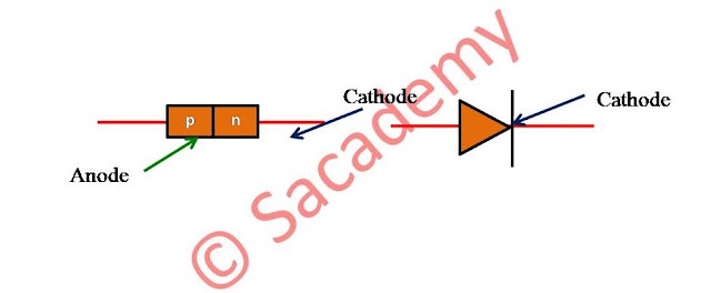
- Power diode is a two layer, two terminal, p-n semiconductor diode.
- The two terminal of diode are called anode and cathode.
Characteristic of power diodes
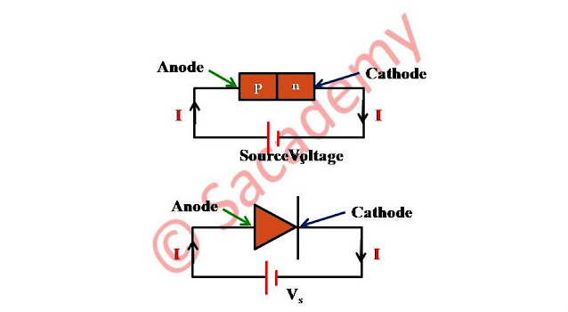
Circuit diagram for characteristic curve of power diode
- When diode is positive with respect to cathode, diode is said to be forward biased.
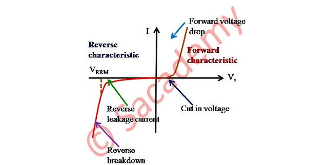
- With increase of Vs from zero value, initially diode current I is zero.
- From Vs = 0 to cut-in voltage (threshold voltage or truth-on voltage), the forward diode current is very small.
- After cut in voltage, the forward diode current increases rapidly and the diode is said to conduct.
- For Si diode, the value of cut-in voltage is 0.7V
- When diode conduct, there is a forward voltage drop of the order of 0.8 to 1V.
Characteristic curve of power diode
- When cathode is positive with respect to anode, the diode is said to be reverse biased.
- In reverse bias condition, a small reverse current, known as leakage current flow in the circuit and this current is of the order of µA or mA.
- The value of leakage current increases slowly with the increase in reverse voltage up to breakdown or avalanche voltage.
- At breakdown voltage, the diode is turned on in the reverse direction.
- The reverse avalanche breakdown of a diode is avoided by operating the diode below specified peak repetitive reverse voltage VRRM.
- PIV = peak inverse voltage of a diode.
- The PIV of a diode is the maximum reverse voltage to which a diode may be subjected during its working. It is same as VRRM.
Diode reverse recovery characteristics
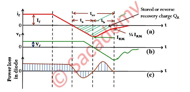
- After the forward diode current decays to zero, the diode continuous to conduct in the reverse direction, due to the presence of stored charges in the two layers.
- The reverse current flows for a time called reverse recovery time trr.
Reverse recovery characteristic of power diode
Reverse recovery time (trr)
- Reverse recovery time is defined as the time between the instant forward diode current becomes zero and the instant reverse recovery current decays to 25% of its reverse peak value IRM.
- trr = ta + tb
- ta : The time between zero crossing of forward current and peak reverse current IRM. During this time the charge stored in depletion region is removed.
- tb : It is measured from the instant of IRM to the instant where 0.25 (or 25%) IRM is reached. During this time the charge from the semiconductor layers is removed.
- During trr, the stored or reverse recovery charge QR must be removed.
Softness factor or S factor
- The ratio of tb and ta is known as softness factor or S-factor.
- The S factor is a measure of the voltage transient that occur during the time, diode recovers.
- Usually the value of softness factor is found to be unity, which indicates low oscillatory reverse recovery process.
- If softness factor is small, then diode has large oscillatory over voltages.
- If S-factor is 1, the diode is called soft-recovery diode.
- If S-factor is less than 1, the diode is called or fast recovery diode. or snappy recovery diode.
- If vf is forward voltage drop across diode, and if is forward current
- vf × if is power loss in diode
- Fig (c) shows that major power loss in a diode occurs during tb
- From fig (a), IRM = ta (di/dt)
- Here IRM = Peak inverse current, and di/dt = Rate of change of reverse current
- If we assume that reverse recovery characteristic of fig. (a) is triangular, then
- QR = ½ IRM × trr ⇒ IRM = 2 (QR / trr)
- ∵ IRM = ta (di/dt) and ta = trr
- Thus trr (reverse recovery time) and IRM (peak inverse current) depends on QR (storage charge) and di/dt (rate of change of current)
- Since QR depends on if (forward diode current)
- So trr and IRM also depends on if.
- So a power electronics engineer must know the value of IRM, QR, S-factor and PIV to design the circuit in which power diodes are used.
To know more about power diode please click here.


Thank you sir for providing such important topics in easy language..